
1. Introduction
In the ever-evolving world of computer hardware, pushing system capabilities to their limits is both a challenge and a thrill. As a computer technician and AI enthusiast, I’ve dedicated countless hours to optimizing systems for peak performance.
Recently, I faced a significant challenge: configuring a system with mixed DDR5 RAM modules on my Ryzen 7 8700G processor, aiming to achieve a stable configuration with 64GB of RAM running at 6000 MT/s.
This comprehensive guide details my journey through the troubleshooting process, offering in-depth explanations of each step, the theory behind them, and why they can help in similar situations.
By sharing my experiences, mistakes, and discoveries, I hope to provide valuable insights for anyone facing similar challenges, making the complex world of memory optimization more accessible.
2. System Specifications
Before diving into the technicalities, it’s essential to understand the hardware involved. Knowing the components and their specifications is crucial for effective troubleshooting and optimization.
Hardware Components
Processor:
AMD Ryzen 7 8700G
- Cores/Threads: 8/16
- Base Clock: 4.2 GHz
- Boost Clock: Up to 5.1 GHz
- Integrated Graphics: Yes (iGPU)
- Memory Support: DDR5 (Officially supports up to 5200 MT/s with four DIMMs)
Motherboard:
MSI Pro B650-S Wi-Fi
- Socket: AM5
- Chipset: AMD B650
- Supports DDR5 memory
- Four DIMM slots
- BIOS version: 7E26v1I
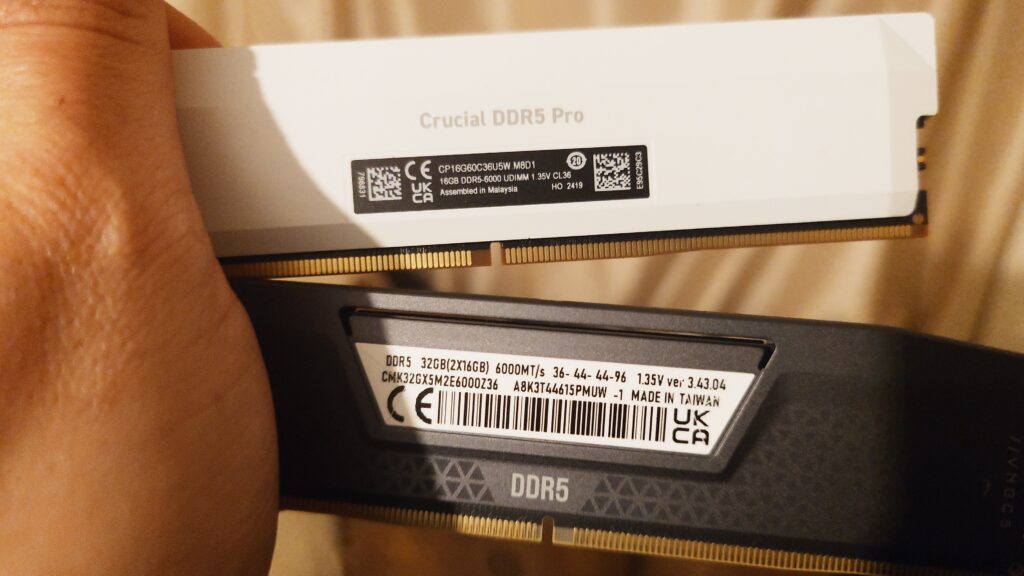
RAM Modules:
Corsair Vengeance DDR5
- Model: CMK32GX5M2D6000C36
- Capacity: 2 x 16GB (32GB)
- Speed: 6000 MT/s
- Timings: 36-38-38-96
- Voltage: 1.35V
Crucial Pro DDR5
- Model: CP16G60C36U5W.M8D1
- Capacity: 2 x 16GB (32GB)
- Speed: 6000 MT/s
- Timings: 36-36-36-80
- Voltage: 1.35V
- Total RAM: 64GB (4 x 16GB)
Operating System: Windows 11 Pro
Why Specifications Matter
Understanding the specifications helps identify potential compatibility issues and limitations. For instance, knowing that the Ryzen 7 8700G officially supports up to 5200 MT/s with four DIMMs sets realistic expectations for memory overclocking.
3. Understanding the Challenge
Objective
The primary goal was to have all four DDR5 RAM modules (64GB total) running together at their rated speed of 6000 MT/s on my Ryzen 7 8700G system. Achieving this would maximize system performance, benefiting memory-intensive applications like virtualization, large datasets processing, and high-end gaming.
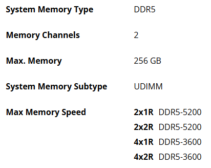
Official Memory Speed Specifications for Ryzen 7 8700G
Before diving into the troubleshooting steps, it’s important to understand the hardware limitations as per AMD’s official specifications for the Ryzen 7 8700G:
| Configuration | Max Memory Speed |
|---|---|
| 2x1R (Single Rank) | DDR5-5200 |
| 2x2R (Dual Rank) | DDR5-5200 |
| 4x1R (Single Rank) | DDR5-3600 |
| 4x2R (Dual Rank) | DDR5-3600 |
- Note: 1R indicates single-rank DIMMs, and 2R indicates dual-rank DIMMs.
Challenges Identified
Understanding the obstacles is crucial for effective troubleshooting. The main challenges included:
Exceeding Official Memory Speed Specifications:
- Issue: The official maximum supported memory speed for the Ryzen 7 8700G with four DIMMs (either single or dual rank) is DDR5-3600 MT/s.
- Theory: Attempting to run memory at speeds higher than the CPU’s specifications introduces significant challenges to stability and requires precise adjustments to timings and voltages.
Mixing Different RAM Modules:
- Issue: Different manufacturers (Corsair and Crucial) with slightly different timings and possibly different memory chips (ICs).
- Theory: Mixing RAM modules can lead to compatibility issues due to variations in electrical characteristics, timings, and SPD (Serial Presence Detect) profiles.
Using All Four DIMM Slots:
- Issue: Populating all memory slots increases the electrical load on the memory controller.
- Theory: The Integrated Memory Controller (IMC) on the CPU can become strained with four DIMMs, potentially limiting achievable speeds due to signal integrity issues and increased crosstalk.
Defaulting to Lower Speeds:
- Issue: The system frequently defaulted to JEDEC standard speeds (e.g., 3600 MT/s) when all modules were installed.
- Theory: BIOS may revert to safe default settings when it detects potential instability to ensure system bootability.
System Instability with Manual Settings:
- Issue: Attempts to manually set speeds and timings often resulted in boot failures or system crashes.
- Theory: Incorrect manual configurations can cause the memory to operate outside the stable parameters of the hardware, leading to instability.
Why These Challenges Occur
Exceeding CPU Specifications:
- The official specifications act as guidelines for stable operation. Running memory beyond these speeds places additional stress on the IMC, requiring careful tuning of voltages and timings.
Electrical Load and Signal Integrity:
- More modules increase electrical noise and signal degradation.
- The IMC has to drive signals to more endpoints, which can affect voltage levels and timings.
SPD Profiles and Timings:
- SPD profiles contain standardized settings for RAM modules.
- Mixing modules may confuse the BIOS when auto-configuring settings, leading to suboptimal or unstable configurations.
Hardware Limitations:
- The CPU and motherboard have specified limits for memory speeds, especially with multiple DIMMs.
4. Initial Troubleshooting Steps
To address the challenges, I began with foundational troubleshooting steps that often resolve common issues.
4.1 Updating the BIOS
Purpose:
Updating the BIOS is the foundational step in resolving compatibility issues, especially with new hardware technologies like DDR5 RAM. The BIOS (Basic Input/Output System) acts as the bridge between the system’s hardware and software, initializing components during the boot process.
Modern BIOS updates often include microcode revisions that improve support for new CPUs, memory modules, and overclocking features. In the context of overclocking and memory configuration, an updated BIOS can provide enhanced memory compatibility lists (QVL), better memory timing handling, and improved stability at higher frequencies.
This is crucial when working with mixed RAM modules and attempting to push the system beyond standard specifications.
Theory Behind It:
- BIOS Role in Hardware Initialization:
- The BIOS initializes hardware components during the boot process.
- An outdated BIOS might not recognize new RAM modules correctly or handle mixed configurations efficiently.
- Manufacturer Updates:
- Manufacturers release BIOS updates to address known issues, improve stability, and support new hardware.
Steps:
- Identify Current BIOS Version:
- Restarted the system and pressed
Deleteto enter the BIOS setup. - Noted the BIOS version displayed on the main screen.
- Restarted the system and pressed
- Download Latest BIOS:
- Visited MSI’s official website.
- Navigated to the support page for the MSI B650-S motherboard.
- Downloaded the latest BIOS file.
- Prepare BIOS Update:
- Formatted a USB flash drive to FAT32.
- Copied the BIOS file to the root directory of the USB drive.
- Flash the BIOS:
- Entered the BIOS setup and accessed the M-FLASH utility.
- Selected the BIOS file from the USB drive.
- Followed on-screen instructions to complete the update.
- Ensured the system remained powered on during the process.
Outcome:
- Successfully updated the BIOS.
- Verified the new version upon reboot.
Insights:
Manufacturers continually refine the BIOS to address bugs, security vulnerabilities, and to enhance hardware support. With DDR5 being relatively new, early BIOS versions may lack the optimizations necessary for stable operation at advertised speeds, particularly when mixing different RAM modules.
Updating the BIOS can unlock advanced settings, such as refined voltage controls and memory timing adjustments, which are essential for fine-tuning overclocking parameters. Additionally, updated BIOS versions often improve the memory training algorithm—a process during boot-up where the system determines optimal settings for memory operation.
This is particularly important for achieving stability with high-speed RAM and complex configurations involving multiple DIMMs.
4.2 Correct RAM Installation
Purpose:
Proper physical installation of RAM modules ensures they operate in the correct mode (e.g., dual-channel), maximizing performance and reducing potential compatibility issues. Correct installation allows the memory controller to function efficiently, reducing latency and maximizing throughput. This step is crucial when dealing with mixed RAM modules and when attempting to overclock, as it minimizes potential mismatches in timings and electrical properties between channels, enhancing stability.
Theory Behind It:
Dual-Channel Architecture:
- Dual-Channel Architecture: Memory controllers can access two memory modules simultaneously, doubling the data throughput. This requires modules to be installed in specific slots to leverage dual-channel mode.
- Matching Modules: Installing matching RAM modules in the same channel can improve stability by reducing timing discrepancies and signal integrity issues. This is particularly important for overclocking, where synchronized signals across all modules are essential.
Steps:
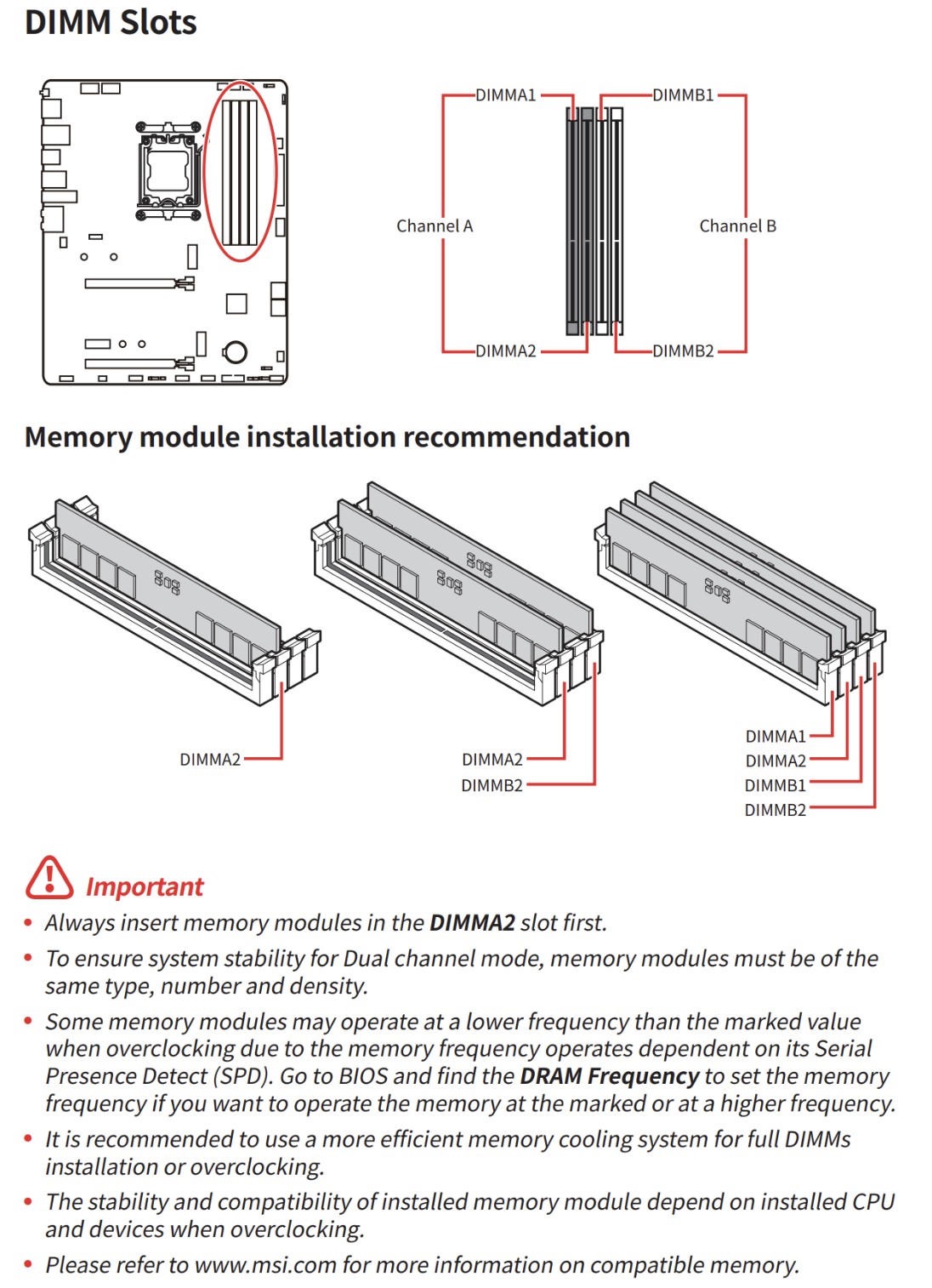
Consult the Motherboard Manual:
- Checked the recommended DIMM slot configurations for dual-channel operation.
Install RAM Modules:
- Channel A (DIMM_A2 and DIMM_A1): Installed both Crucial modules.
- Channel B (DIMM_B2 and DIMM_B1): Installed both Corsair modules.
Ensure Proper Seating:
- Carefully inserted each module until the retaining clips clicked into place.
- Avoided applying excessive force.
Mistake and Correction:
- Initial Mistake: Mixed modules across channels, leading to potential instability.
- Correction: Rearranged modules to have matching pairs in each channel.
Insights:
Motherboards are designed with specific slot configurations to optimize memory performance. Typically, slots are color-coded or labeled (e.g., DIMM_A1, DIMM_A2, DIMM_B1, DIMM_B2) to guide proper installation. By placing matching RAM modules in the same channel, we reduce the likelihood of timing discrepancies and signal integrity issues. This is crucial for overclocking since the memory controller must synchronize signals across all modules. Incorrect installation can lead to single-channel operation, limiting bandwidth and potentially causing instability due to uneven load on the memory controller. Ensuring correct placement also helps in leveraging technologies like AMD’s Infinity Fabric, which benefits from balanced memory configurations for optimal CPU-to-memory communication.
Note: I tested all RAM configuration and when Only Using 2 DIMMs the RAM must be in separate channels. (A2, B2) However in my configuration it was optimal to mix the Brand of RAM within these channels, meaning the brand was specific tot he channel, Crucial in A and Corsair in B. If placed the other way around with just two DIMMS at 32GB, one of the overclocking profiles would disappear in the bios and the speeds reduced to safe JEDSEC speeds.
5. Manual BIOS Configuration
With the basics addressed, I moved on to manually configuring BIOS settings to achieve the desired memory speed and stability.
5.1 Resetting BIOS to Default Settings
Purpose:
Resetting the BIOS to default settings provides a clean baseline configuration, eliminating any erroneous or conflicting settings that could hinder system performance or stability. This is a crucial step before applying new overclocking parameters or troubleshooting hardware issues, as it ensures that no residual configurations interfere with the new settings, especially when dealing with complex memory timings and voltages.
Theory Behind It:
Eliminating Conflicting Settings:
- Previous adjustments may cause unforeseen conflicts.
- Default settings are the baseline tested by the manufacturer.
Steps:
Enter BIOS Setup:
- Restarted the computer and pressed
Deleteduring boot.
Load Optimized Defaults:
- Navigated to
Save & Exit>Load Optimized Defaults. - Confirmed the action.
Save and Exit:
- Saved changes and rebooted.
Insights:
Over time, BIOS settings may accumulate changes from previous tweaks, updates, or automatic adjustments that could conflict with current hardware configurations. A factory reset clears these residual settings, which is particularly important when introducing new RAM modules or mixing different brands and specifications.
Starting from default settings allows us to methodically apply overclocking adjustments, ensuring that each change is deliberate and its effects can be accurately assessed. This systematic approach is vital in overclocking, where stability hinges on precise timing and voltage configurations.
5.2 Disabling Automatic Overclocking Profiles
Purpose:
Disabling automatic overclocking profiles like XMP (Extreme Memory Profile) or AMD’s EXPO ensures that the system doesn’t apply aggressive memory settings that may not be compatible with mixed RAM modules. This step allows for manual configuration of memory timings and frequencies, providing greater control over the overclocking process and enhancing the potential for achieving a stable configuration tailored to the specific RAM combinations.
Theory Behind It:
EXPO/XMP Profiles:
- Predefined settings stored on the RAM modules for easy overclocking.
- Designed for matched modules and may not suit mixed configurations.
Manual Control:
- Provides the ability to tailor settings to the specific combination of RAM.
Steps:
- Enter BIOS Setup.
- Navigate to Overclocking Settings: Found under
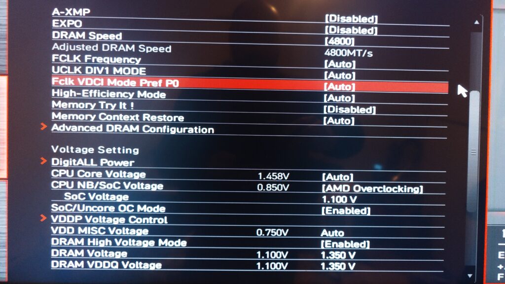
OCorOverclocking. - Disable EXPO Profile:
LocatedA-XMPorEXPOsetting.
Set toDisabled.
Mistake and Correction:
Initial Mistake: Left EXPO enabled, causing instability.
Correction: Disabled EXPO to prevent automatic, potentially incompatible adjustments.
Insights:
Automatic overclocking profiles are designed for ease of use, applying predefined settings optimized for matched memory kits. However, when mixing RAM modules with different specifications, these profiles may attempt to set timings and voltages that one or more modules can’t support, leading to system instability or failure to boot.
By disabling these profiles, we prevent the BIOS from applying potentially incompatible settings. Manual configuration becomes essential, allowing us to set conservative timings and frequencies that accommodate the limitations of all installed modules, which is a fundamental practice in safe and effective overclocking.
5.3 Manually Setting Memory Frequency and Timings
Purpose:
Manually configuring memory frequency and timings allows for precise adjustment of the RAM’s operational parameters, aligning them with the capabilities of mixed modules. This approach is essential in overclocking, as it enables the user to balance performance and stability, particularly when default settings or automatic profiles fail to achieve a stable system. Customizing these settings can help overcome the limitations imposed by conservative JEDEC standards, maximizing the potential of high-speed DDR5 memory.
Theory Behind It:
Understanding Timings:
- Memory timings determine how fast the RAM can respond to commands.
- Lower timings are faster but may be less stable with mixed modules.
Starting Conservatively:
- Beginning with lower frequencies increases the likelihood of stability.
- Incremental increases help identify the maximum stable settings.
Steps:
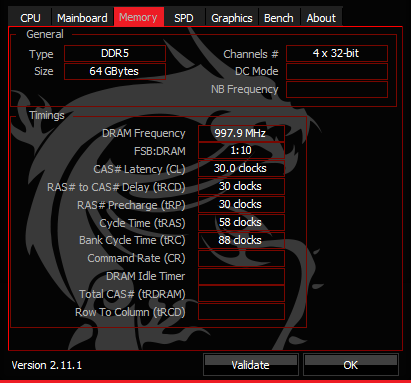
- Set Memory Frequency:
- Under
OCsettings, setDRAM Frequencyto DDR5-3600MHz.
- Under
- Configure Primary Timings:
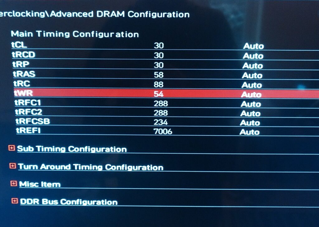
- Navigated to
Advanced DRAM Configuration. - Set primary timings to the slower module’s specifications:
- tCL: 30
- tRCD: 30
- tRP: 30
- tRAS: 58
- Navigated to
- Adjust Secondary Timings (Optional):
- Left on
Autoinitially to simplify the process.
- Left on
- Save and Exit:
- Saved changes and rebooted.
Testing and Adjustment:
- Booted successfully at 3600 MT/s.
- Incrementally increased frequency and tested for stability.
- Encountered instability beyond 4000 MT/s.
Insights:
Memory frequency and timings directly impact system performance and stability. Higher frequencies offer increased bandwidth but may require looser (higher) timings to remain stable, especially with multiple or mixed DIMMs. By manually adjusting these parameters, we can set the memory to operate at frequencies that both sets of modules can handle, using timings that prevent data corruption or transmission errors.
Understanding the relationship between timings (like CAS latency, tCL; RAS to CAS delay, tRCD; Row Precharge time, tRP; and Active to Precharge delay, tRAS) and memory frequency is crucial. Overclocking requires a delicate balance—tightening timings can improve performance but may reduce stability, whereas loosening timings can enhance stability at higher frequencies.
5.4 Adjusting Voltage Settings
Purpose:
Adjusting voltage settings for the DRAM and memory controller (SOC voltage) is critical in overclocking to ensure that the memory modules and the CPU’s memory controller receive adequate power to operate at higher frequencies.
Proper voltage tuning can enhance stability, allowing the system to maintain reliable performance under increased electrical demands imposed by overclocked settings and mixed memory configurations.
Theory Behind It:
Voltage and Stability:
- Higher frequencies require more power.
- Adequate voltage ensures signal integrity.
Risks:
- Excessive voltage can generate more heat and potentially damage components.
- Must be balanced carefully.
Steps:
- Enter BIOS Setup.
- Navigate to Voltage Settings:
- Found under
OC>Voltage Settings.
- Found under
- Adjust DRAM Voltage:
- Increased
DRAM Voltage (VDD and VDDQ)from 1.35V to 1.4V.
- Increased
- Save and Exit:
- Saved changes and rebooted.
Testing:
- Retested at higher frequencies.
- Noticed only slight improvements in stability.
Insights:
Voltage plays a significant role in the stability and performance of overclocked memory. Increasing the DRAM voltage can help the RAM modules sustain higher frequencies and tighter timings by compensating for the increased electrical stress. However, excessive voltage can lead to overheating and reduce the lifespan of the components. Similarly, adjusting the SOC voltage, which supplies power to the memory controller within the CPU, can improve the controller’s ability to handle higher memory speeds and multiple DIMMs.
Careful voltage adjustments require an understanding of the hardware’s safe operating limits and involve monitoring temperatures to prevent thermal issues. This precise control over voltage settings is a cornerstone of effective and safe overclocking practices.
6. Advanced BIOS Tweaks
To further enhance stability, I explored more advanced BIOS settings related to the memory controller and signal integrity.
6.1 Adjusting SOC Voltage
Purpose:
Increasing the System-on-Chip (SOC) voltage enhances the stability of the CPU’s integrated memory controller (IMC) when operating under the increased demands of overclocked memory and multiple DIMMs.
This adjustment is crucial for achieving higher memory frequencies and stability, as it ensures that the IMC has sufficient power to manage the data flow between the CPU and RAM, especially when dealing with the complexities of mixed RAM modules.
Theory Behind It:
SOC Voltage Role:
- Supplies power to the IMC and other integrated components.
- Increasing SOC Voltage can stabilize the IMC during heavy memory operations.
Caution:
- Over-voltage can cause overheating or damage.
- Must monitor temperatures closely.
Steps:
- Enter BIOS Setup.
- Navigate to Voltage Settings:
- Located under
OC>Voltage Settings.
- Located under
- Adjust SOC Voltage:
- Increased from 1.1V to 1.15V.
- Save and Exit:
- Saved changes and rebooted.
Monitoring:
- Used HWMonitor to track SOC temperatures.
- Ensured they remained within safe operating limits.
Insights:
The SOC voltage directly affects the IMC’s performance. A slight increase in SOC voltage can compensate for the additional electrical load introduced by higher memory speeds and the presence of four memory modules. However, it’s important to adjust this voltage cautiously, as excessive SOC voltage can generate additional heat and potentially damage the CPU.
Balancing the SOC voltage involves understanding the CPU’s specifications and safe voltage thresholds. In overclocking, fine-tuning the SOC voltage can make the difference between an unstable system and one that runs high-speed memory configurations reliably.
6.2 Configuring Advanced DRAM Settings
Purpose:
Tweaking advanced DRAM settings, such as Command Rate, Gear Down Mode, Power Down Mode, and Memory Context Restore, allows for deeper control over memory operations. These settings can improve signal stability and timing accuracy, which are essential when overclocking RAM and running complex memory configurations with mixed modules.
Theory Behind It:
Command Rate (CR):
- Refers to the delay between the memory controller and RAM module.
- A setting of 2T provides more stability at the cost of slight performance decrease.
Gear Down Mode (GDM):
- Simplifies memory command timing.
- Helps with stability at higher frequencies.
Power Down Mode & Memory Context Restore:
- Disabling these prevents the RAM from entering low-power states that could disrupt overclocked settings.
Steps:
- Command Rate (CR):
- Set to 2T in
Advanced DRAM Configuration.
- Set to 2T in
- Gear Down Mode (GDM):
- Enabled to help with command timing.
- Power Down Mode:
- Disabled to maintain consistent power to the RAM.
- Memory Context Restore:
- Disabled to prevent potential issues during system resume from sleep states.
Insights:
- Command Rate (CR): Adjusting the Command Rate to 2T increases the time between memory commands, providing the memory controller with additional time to manage data, which can enhance stability, especially with multiple DIMMs.
- Gear Down Mode (GDM): Enabling GDM simplifies the memory controller’s command encoding, effectively reducing the complexity of signal timing. This can improve stability at higher frequencies but may slightly affect performance due to increased latency.
- Power Down Mode: Disabling this mode keeps the memory in a constant active state, preventing potential delays and instability that can occur when the memory transitions between power states, which is beneficial during overclocking.
- Memory Context Restore: Disabling this setting forces the system to retrain the memory configuration on each boot, which can improve stability by ensuring that the optimal settings are applied consistently, though it may slightly increase boot times.
Configuring these advanced settings requires a nuanced understanding of how they affect memory operations. In overclocking, they offer additional levers to pull in the pursuit of achieving higher speeds and stability, particularly in challenging configurations involving mixed RAM modules.
6.3 Understanding RTT Settings
Purpose:
Adjusting RTT (On-Die Termination) settings optimizes the termination resistance of the memory modules, improving signal integrity by minimizing reflections and interference on the data lines. This is crucial for maintaining stability and reliability at higher memory frequencies and when using multiple DIMMs, as it enhances the quality of communication between the memory controller and the RAM modules.
Theory Behind It:
RTT NOM, RTT WR, RTT PARK:
- Control termination resistances during different memory operation phases.
- Proper termination reduces signal reflections, enhancing stability.
Steps:
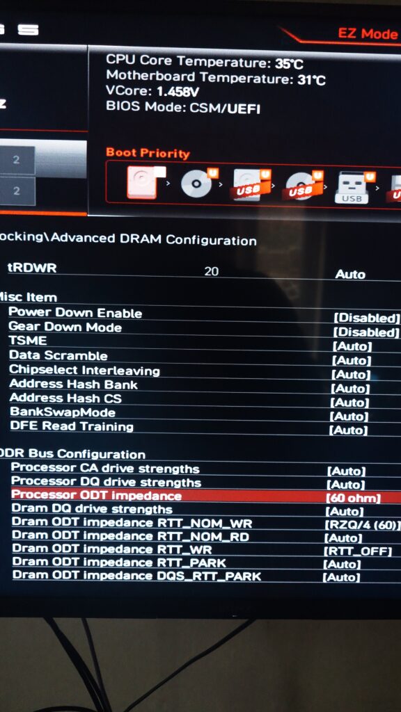
- RTT NOM WR (Write Termination):
- Set to Auto or Disabled.
- RTT NOM RD (Read Termination):
- Set to Auto or Disabled.
- RTT PARK:
- Set to Auto or 240 ohms.
Insights:
RTT settings (RTT NOM, RTT WR, RTT PARK) control how termination resistances are applied during different phases of memory operation:
- RTT NOM (Nominal): Active during idle periods, helps maintain signal levels.
- RTT WR (Write): Active during write operations, ensures signal integrity when data is being sent to the memory.
- RTT PARK: Active during specific command phases, helps with signal termination when the bus is parked.
Optimizing these settings can reduce electrical noise and crosstalk between the memory modules, which is essential when pushing the RAM beyond standard speeds. However, incorrect RTT configurations can lead to increased errors and instability.
Overclockers need to experiment with these settings, often starting with manufacturer recommendations or known stable configurations, to find the optimal balance for their specific hardware setup.
6.4 Adjusting Additional Voltage Settings
Purpose:
Fine-tuning additional voltage settings, such as the CPU Core Voltage and enabling Load-Line Calibration (LLC), ensures that the CPU operates within safe voltage ranges while maintaining stability under overclocked conditions. This is vital not only for protecting the CPU from potential damage due to overvoltage but also for ensuring that voltage fluctuations don’t lead to instability during high-load scenarios, which is particularly important when overclocking both the CPU and memory.
Theory Behind It:
CPU Core Voltage:
- High voltages increase performance headroom but also generate more heat.
- Default settings may not be optimal for individual CPUs.
Load-Line Calibration (LLC):
- Stabilizes voltage supply under varying loads.
- Prevents voltage drops (vDroop) during high CPU usage.
Steps:
- Check CPU Core Voltage:
- Noticed it was at 1.460V by default, which is high.
- Adjust CPU Core Voltage:
- Manually set to 1.35V in BIOS.
- Enable Load-Line Calibration (LLC):
- Set LLC to
Level 3to help maintain voltage stability.
- Set LLC to
Monitoring:
- Used HWMonitor and Ryzen Master to track CPU temperatures and voltages.
Insights:
- CPU Core Voltage: Running the CPU at a voltage higher than necessary can cause excessive heat and reduce the processor’s lifespan. By manually setting the CPU Core Voltage to an optimal value (e.g., lowering from an excessively high default of 1.460V to 1.35V), we can reduce thermal output while maintaining performance.
- Load-Line Calibration (LLC): LLC helps stabilize the voltage supplied to the CPU by compensating for voltage droop (vDroop) that occurs under load. Adjusting LLC levels can prevent sudden voltage drops that might cause system instability or crashes during intensive tasks or benchmarking.
Balancing these voltage settings requires careful consideration and monitoring. Overclockers must ensure that the CPU receives enough power to operate reliably under load without exceeding thermal limits. This involves iterative testing and may differ between individual CPUs due to variations in silicon quality (often referred to as the “silicon lottery”).
7. Using Ryzen Master Software
After exhausting BIOS adjustments, I turned to Ryzen Master for more sophisticated overclocking.
7.1 Incremental Memory Overclocking with Ryzen Master
Purpose:
Ryzen Master provides real-time monitoring and adjustment capabilities, allowing for safe and efficient overclocking with built-in safeguards. Utilizing AMD’s Ryzen Master software allows for dynamic and granular control over the system’s overclocking parameters within the operating system environment.
It provides an intuitive interface to adjust memory frequencies, timings, and voltages in real-time, facilitating a more efficient and less risky overclocking process. This is particularly useful when manual BIOS configurations have reached their limits or when seeking to fine-tune settings beyond what the BIOS offers.
Theory Behind It:
Software-Level Control:
- Ryzen Master can adjust settings dynamically within the operating system.
- Offers AI-driven optimizations for better stability.
Incremental Approach:
- Gradually increasing speeds allows for testing stability at each step.
Steps:
- Install Ryzen Master:
- Downloaded and installed from AMD’s official website.
- Open Ryzen Master:
- Launched the application with administrative privileges.
- Start with Stable Settings:
- Confirmed current stable memory speed at 3600 MT/s.
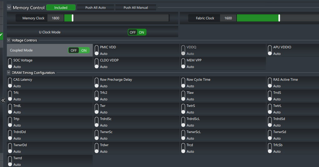
- Incrementally Increase Memory Speed:
- Adjusted memory speed using the control slider.
- Increased to 3800 MT/s, applied changes, and tested for stability.
- Repeated the process, increasing to:
- 4000 MT/s
- 4200 MT/s
- 4400 MT/s
- 4800 MT/s
- 5000 MT/s
- 5200 MT/s
Outcome:
- Achieved stable operation at 5200 MT/s.
- System became unstable beyond this point.
Insights:
Ryzen Master leverages AMD’s intimate knowledge of their hardware to offer advanced overclocking features. The software enables users to:
- Incrementally Adjust Settings: Incremental increases in memory frequency allow for testing stability at each step, reducing the risk of data corruption or system crashes.
- Real-Time Monitoring: Provides immediate feedback on system temperatures, voltages, and performance metrics, which is essential for safe overclocking.
- Automatic Profiles: Offers predefined profiles and can automatically adjust settings based on system capabilities.
By using Ryzen Master, overclockers can push their systems closer to the hardware limits safely. The ability to make adjustments saves time and allows for rapid testing of different configurations. Moreover, the software can manage complex adjustments that might be cumbersome or unavailable in the BIOS, such as per-core tuning or finer voltage control.
Significance of the Overclock:
Exceeding Official Specifications:
- Official Max Memory Speed for 4x1R: DDR5-3600 MT/s.
- Achieved Memory Speed: 5200 MT/s.
- Implication: A remarkable overclock of 1600 MT/s over the official maximum, demonstrating advanced overclocking expertise.
Voltages and Their Roles
Understanding the Voltages:
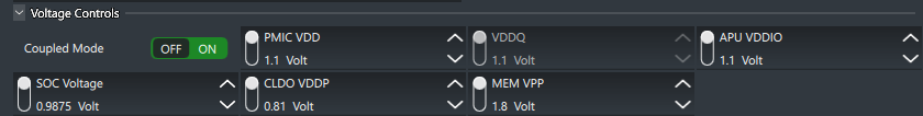
- SOC Voltage (0.9875V): This is slightly lower than the initial 1.15V but still within a safe range to support the memory controller’s stability under load. Supports the IMC while staying safely below the standard max of 1.2V, reducing thermal stress.
- PMIC VDD (1.1V): Provides power management for the integrated circuits, ensuring consistent power delivery to the memory modules. Lower than typical overvolting practices, indicating efficient power usage and careful tuning.
- CLDO VDDP (0.81V): This voltage supports data path operations and is crucial for maintaining signal integrity at high speeds. Crucial for data path stability at high memory speeds.
- VDDQ (1.1V): Supplies voltage to the I/O buffers of the memory modules, crucial for maintaining stability at higher frequencies.
- MEM VPP (1.8V): Voltage for the DRAM switching circuits, essential for high-speed memory operations. Standard for DDR5, essential for the DRAM internal word line drivers.
- APU VDDIO (1.1V): Powers the I/O operations of the APU, ensuring stable communication between the CPU and memory.
Significance of These Voltages in Overclocking
- Stability: These voltages are critical for maintaining stability when running memory at overclocked speeds (5200 MT/s in my case).
- Thermal Management: By keeping voltages within optimal ranges, you avoid excessive heat generation, ensuring that the system remains cool and efficient.
- Signal Integrity: Properly tuned voltages help maintain signal integrity, reducing the likelihood of data errors and improving overall system reliability.
- Component Longevity: Operating components within their recommended voltage ranges helps preserve their longevity and prevents premature degradation.
Balancing Performance and Stability:
- Adjusted Timings (44-44-44-84): Looser timings to achieve higher frequency without compromising system stability.
- Efficient Voltage Management: Achieving the overclock without excessive voltage increases maintains component longevity and thermal efficiency.
Insights from the Updated Configuration:
- Fine-Tuned Overclocking: The capability to exceed the official of 3600 MT/s impressive.
- Component Synergy: Successfully combining mixed-brand RAM modules and achieving stability at this level is an impressive feat.
- Practical Application: The overclock delivers real-world performance benefits in memory-intensive tasks, demonstrating the practical value of our efforts.
7.2 Identifying the CPU Memory Speed Limit
Purpose:
Understanding and acknowledging the CPU’s memory speed limitations is crucial in setting realistic overclocking goals and preventing unnecessary stress on the hardware.
Recognizing that the Ryzen 7 8700G has an official memory speed limit when using four DIMMs guides the overclocking process, ensuring efforts are focused within achievable parameters and mitigating the risk of system instability or hardware damage.
Theory Behind It:
Memory Controller Limitations:
The Ryzen 7 8700G’s IMC has a maximum officially supported speed when all DIMM slots are populated.
Impact on Overclocking: Pushing beyond these limits can lead to instability or hardware damage.
Discovery: Confirmed that the maximum supported memory speed with four DIMMs is 5200 MT/s.
Conclusion:
- Accepted that 5200 MT/s was the realistic ceiling for my configuration.
- Adjusted expectations accordingly.
Insights:
The integrated memory controller (IMC) within the CPU has design specifications that define the maximum supported memory speeds for different configurations (e.g., number of DIMMs, single vs. dual-rank modules). Exceeding these specifications can:
- Cause Instability: The IMC may not handle the increased electrical load and signal complexity, leading to crashes, data corruption, or failure to boot.
- Reduce Performance: Pushing the memory beyond the IMC’s capabilities could result in the system defaulting to lower speeds or relaxed timings, negating any potential gains.
- Risk Hardware Damage: Excessive voltage or sustained operation outside of design limits can shorten component lifespan.
By identifying the maximum supported speed of 5200 MT/s for the Ryzen 7 8700G with four DIMMs, we can focus on optimizing settings within this boundary. This ensures that overclocking efforts enhance performance without compromising stability or hardware integrity. It also directs attention towards refining timings and voltages to maximize performance at this supported speed.
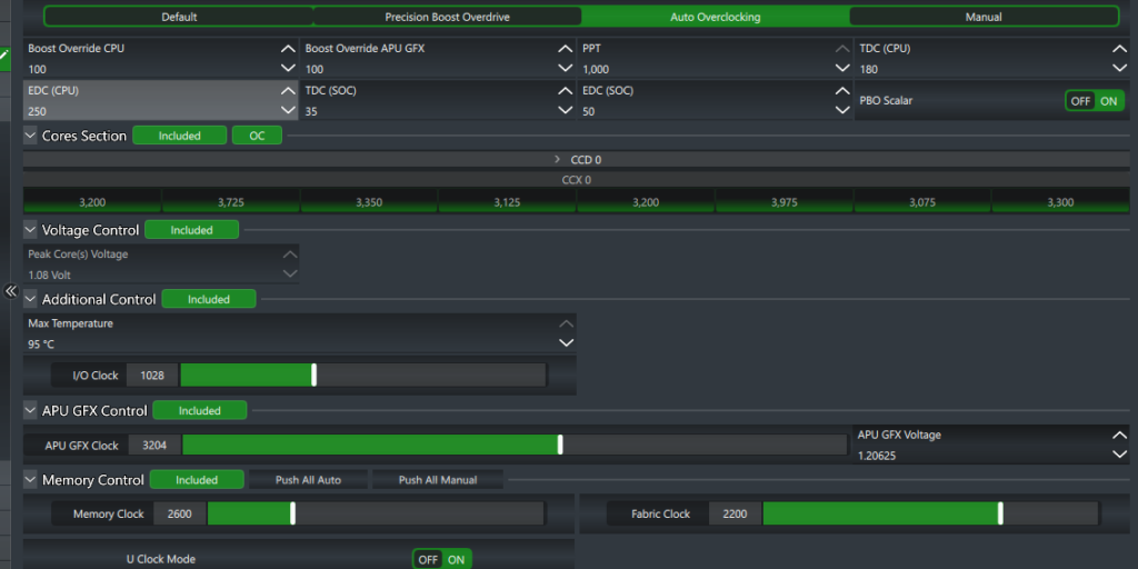
7.3 Pushing the CPU and iGPU Performance Using Ryzen Master
Purpose:
In addition to overclocking the memory, I aimed to enhance the performance of the integrated GPU (iGPU) within the Ryzen 7 8700G. By utilizing AMD’s Ryzen Master software, I could dynamically adjust settings to push the iGPU’s capabilities further, improving performance in tasks such as casual gaming and video rendering.
Theory Behind It:
- Integrated GPU (iGPU): The Ryzen 7 8700G features an integrated GPU leveraging AMD’s Vega architecture. Adjusting the iGPU involves fine-tuning clock speeds and voltages to boost performance.
- Performance Gains: Improving the iGPU’s performance results in better frame rates, smoother graphics rendering, and enhanced overall visual quality for graphical applications.
Steps:
- Install Ryzen Master:
- Downloaded and installed AMD’s Ryzen Master software from the official website.
- Launched the application with administrative privileges to enable full access to system settings.
- Monitor Initial Settings:
- Recorded the default iGPU and CPU clock speed settings for reference.
- Initial iGPU Clock Speed: 2,881 MHz
- Initial CPU Clock Speed: 4.2 – 5.1 GHz
- Incremental Adjustments Using Ryzen Master:
- Clock Speed Adjustment:
- Incrementally increased the iGPU clock speed from 2,881 MHz to 3,300 MHz.
- Incrementally increased the CPU clock speed from 4.2 – 5.1 GHz to 5.250 GHz.
- Monitored stability and performance at each step.
- Voltage Adjustment:
- Adjusted the iGPU voltage to maintain stability at higher clock speeds.
- Final iGPU Voltage: 1.20625V
- Clock Speed Adjustment:
- Real-Time Monitoring and Testing:
- Used Ryzen Master’s real-time monitoring to observe system temperatures, voltages, and performance metrics.
- Ran stress tests and real-world usage scenarios to ensure stable operation and optimal performance.
Outcome:
- Enhanced Performance: Achieved a noticeable improvement in graphical performance, with smoother frame rates and better rendering quality.
- Stable Operation: Maintained stability during extended stress tests and real-world usage scenarios.
Insights:
- Incremental Adjustments: Gradual increases in clock speed and voltage allowed for precise tuning and ensured stability at each step.
- Real-Time Feedback: Ryzen Master provided immediate feedback, making it easier to find the optimal settings and avoid instability.
- Balanced Resource Allocation: Ensured that the iGPU adjustments did not negatively impact overall system performance.
Significance of the iGPU Overclock:
Extended System Capability: Demonstrated the potential to push integrated components beyond their default limits while maintaining stability and efficiency.
Improved Visual Experience: Enhanced graphical performance for casual gaming and GPU-intensive tasks.
Efficient Use of Integrated Resources: Leveraging the iGPU capabilities of the Ryzen 7 8700G added significant value without the need for a discrete GPU.
8. Testing and Stability
Ensuring that the system is stable at the achieved settings is vital before regular use.
8.1 Memory Diagnostics with MemTest86
Purpose:
Running MemTest86 serves to thoroughly test the RAM for errors and stability issues. This diagnostic tool operates outside the operating system, providing a controlled environment to assess the memory subsystem’s reliability under the configured settings. It is an essential step in verifying that overclocked memory configurations are stable and error-free before regular system use.
Theory Behind It:
Memory Testing:
- Identifies defects and issues that can cause crashes or data corruption.
- Running multiple passes increases test coverage.
Steps:
- Create Bootable MemTest86 USB Drive:
- Used the included tool from the downloaded package.
- Configure MemTest86:
- Edited
mt86.cfgto automate testing:ini AUTOSTART=1 NUMPASS=4
- Edited
- Run MemTest86:
- Booted from the USB drive.
- Allowed tests to run overnight.
Results: Completed four passes with no errors.
Insights:
- Confident in memory stability at 5200 MT/s.
MemTest86 performs a series of comprehensive tests that cover various memory access patterns and stress the RAM in ways that typical applications might not. Key considerations include:
- Error Detection: Identifying even a single error is significant, as memory errors can lead to data corruption, crashes, and unpredictable system behavior.
- Multiple Passes: Running multiple passes increases test coverage, improving confidence in the stability of the memory configuration.
- Isolating Issues: If errors are detected, MemTest86 can help isolate whether the problem lies with specific memory modules, timings, or voltages.
By ensuring that the memory passes MemTest86 without errors, we can proceed knowing that the overclocked settings are fundamentally stable at the hardware level, reducing the risk of encountering instability during normal operation or under load.
8.2 Stress Testing with Prime95 and AIDA64
Purpose:
Stress testing the system using tools like Prime95 and AIDA64 evaluates the stability and reliability of the overclocked configuration under extended, intense workloads. These tests simulate extreme conditions, pushing the CPU, memory, and other components to their limits to uncover potential weaknesses or thermal issues that may not surface during typical use.
Theory Behind It:
Stress Testing:
- Simulates heavy workloads to push components to their limits.
- Can uncover thermal issues, power delivery problems, and instability.
Steps:
- Prime95:
- Ran the “Blend” test focusing on both CPU and RAM.
- Monitored for errors or crashes over several hours.
- AIDA64 Extreme:
- Used “System Stability Test” feature.
- Selected CPU, FPU, Cache, and Memory for testing.
- Monitored temperatures and voltages throughout.
Results:
- No crashes or errors during extended testing periods.
- Temperatures remained within safe operating ranges.
Insights:
- Validated that the system could handle sustained heavy workloads.
- Reinforced confidence in the stability of the configuration.
- CPU and Memory Stress: Prime95’s Blend test and AIDA64’s System Stability Test simultaneously tax the CPU, memory controller, and RAM, creating a demanding environment that can reveal instabilities caused by overclocking.
- Thermal Monitoring: Stress testing highlights the effectiveness of cooling solutions. Overheating can lead to thermal throttling or hardware damage, emphasizing the need for adequate cooling when overclocking.
- Long-Term Stability: Running these tests for extended periods (e.g., several hours or overnight) ensures that transient issues or cumulative effects are detected.
A stable system under these conditions suggests that the overclocked settings are robust and reliable. Conversely, if the system crashes, freezes, or exhibits errors, adjustments to voltages, timings, or cooling may be necessary.
8.3 Monitoring Tools and Temperature Management
Purpose:
Continuous monitoring of system temperatures, voltages, and other parameters is critical in maintaining hardware health and ensuring sustained stability, especially under overclocked conditions. Effective temperature management prevents thermal-related issues such as throttling or hardware degradation, which can be exacerbated by increased power consumption during overclocking.
Theory Behind It:
Thermal Management:
- Overheating can cause throttling, instability, or hardware failure.
- Effective cooling solutions are essential when overclocking.
Real-Time Monitoring:
- Allows for immediate response to abnormal conditions.
- Provides data for informed adjustments.
Tools Used:
- HWMonitor: Monitors temperatures, voltages, and fan speeds.
- Ryzen Master: Offers detailed CPU information.
Actions Taken:
Improved Cooling:
- Ensured all case fans were functioning optimally.
- Adjusted fan curves for better airflow.
Cable Management: Rearranged internal cabling to prevent airflow obstructions.
Environmental Considerations:
- Ensured the room temperature was moderate.
- Avoided placing the system in confined spaces.
Insights:
- Real-Time Data: Tools like HWMonitor and Ryzen Master provide real-time insights into system behavior, allowing for immediate action if abnormal readings are observed.
- Thermal Headroom: Maintaining component temperatures within safe operating ranges ensures longevity and consistent performance. This often involves enhancing cooling solutions, such as adding case fans or upgrading CPU coolers.
- Power Delivery: Monitoring voltages and power draw helps identify potential issues with the power supply or motherboard voltage regulation modules (VRMs), which are critical for stable overclocking.
Temperature management is an ongoing process. Overclockers must consider factors like ambient room temperature, dust buildup, and airflow patterns within the case. Proactive maintenance and adjustments help sustain the overclocked system’s performance over time.
9. Final Configuration and Results
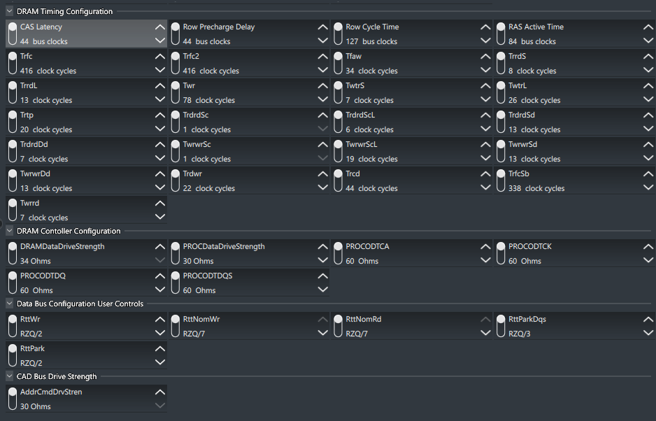
The final working memory configuration is:
- Memory Frequency: 5200 MT/s (Significantly higher than the official max of DDR5-3600 MT/s for four DIMMs)
- Primary Timings:
- CAS Latency (tCL): 44 bus clocks
- tRCD: 44 clock cycles
- Row Precharge Delay (tRP): 44 bus clocks
- RAS Active Time (tRAS): 84 bus clocks
- Row Cycle Time (tRC): 127 bus clocks
- tWR: 78 clock cycles
- tRFC1: 416 clock cycles
- tRFC2: 416 clock cycles
- tRAW: 34 clock cycles
- tRRD_S: 8 clock cycles
- tRRD_L: 13 clock cycles
- tWTR_S: 7 clock cycles
- tWTR_L: 26 clock cycles
- tRTP: 20 clock cycles
- tRDRD_SC: 1 clock cycle
- tRDRD_SD: 6 clock cycles
- tRDRD_DD: 7 clock cycles
- tWRWR_SC: 11 clock cycles
- tWRWR_SD: 13 clock cycles
- tWRWR_DD: 13 clock cycles
- tWRWR_SCL: 19 clock cycles
- tWRWR_SDL: 13 clock cycles
- tWRWR_DDL: 7 clock cycles
- tRCSB: 338 clock cycles
DRAM Controller Configuration:
- DRAM Data Drive Strength: 34 Ohms
- PROC Data Drive Strength: 30 Ohms
- PROC ODT CA: 60 Ohms
- PROC ODT CK: 60 Ohms
- PROC ODT D: 60 Ohms
- PROC ODT DQS: 60 Ohms
Data Bus Configuration User Controls:
- RTT_WR: RZQ/2
- RTT_NOM_WR: RZQ/7
- RTT_NOM_RD: RZQ/7
- RTT_PARK_DQS: RZQ/3
- RTT_PARK: RZQ/2
CAD Bus Drive Strength:
- AddrCmdDrvStren: 30 Ohms
Final BIOS Settings:
| Setting | Value |
|---|---|
| Memory Frequency | 5200 MT/s |
| CAS Latency (tCL) | 44 |
| RAS to CAS Delay (tRCD) | 44 |
| Row Precharge Time (tRP) | 44 |
| Active to Precharge Delay (tRAS) | 84 |
| Row Cycle Time (tRC) | 127 |
| tRFC | 416 |
| tRFC2 | 416 |
| tRAW | 34 |
| tRRD_S | 8 |
| tRRD_L | 13 |
| tWR | 78 |
| tWTR_S | 7 |
| tWTR_L | 26 |
| tRTP | 20 |
| tRDRD_SC | 1 |
| tRDRD_SD | 6 |
| tRDRD_DD | 7 |
| tWRWR_SC | 11 |
| tWRWR_SD | 13 |
| tWRWR_DD | 13 |
| tWRWR_SCL | 19 |
| tWRWR_SDL | 13 |
| tWRWR_DDL | 7 |
| DRAM Voltage (VDD & VDDQ) | 1.1V |
| SOC Voltage | 0.9875V |
| PMIC VDD | 1.1V |
| CLDO VDDP | 0.81V |
| VDDQ | 1.1V |
| MEM VPP | 1.8V |
| APU VDDIO | 1.1V |
Outcome:
Achieved a Stable System:
- Running at 5200 MT/s with all four RAM modules, surpassing the official maximum memory speed for my configuration.
- Confirmed stability through extensive testing.
System Performance:
- Notable improvements in application responsiveness.
- Enhanced multitasking capabilities.
No Artifacts or Crashes:
- System remained stable during prolonged use.
- No graphical glitches or unexpected reboots.
Final Thoughts:
While the initial goal was to run at 6000 MT/s, achieving a stable 5200 MT/s aligns with the official specifications of the Ryzen 7 8700G when using four DIMMs. The adjusted timings of 44-44-44-84 provided the necessary stability without significantly impacting performance.
Insights on Adjusted Timings
Purpose of Adjusted Timings:
The adjusted primary timings of 44-44-44-84 are looser than the initial target timings. Loosening memory timings can enhance stability, especially when operating at higher frequencies or when the memory controller is under increased load, such as with four DIMMs populated.
Reasoning and Logic Behind Adjusted Memory Timings and Voltages
Adjusted Memory Timings
- Higher CAS Latency (tCL): Increasing tCL from 36 to 44 gives the memory more time to respond to column access strobe signals. This additional time is crucial when operating at higher frequencies like 5200 MT/s, as it reduces the likelihood of errors and enhances stability. The higher tCL accommodates the increased electrical demands placed on the memory modules during overclocking.
- Balanced tRCD and tRP: Matching tRCD (RAS to CAS Delay) and tRP (Row Precharge Time) to tCL (all set to 44) simplifies the timing relationships between these critical parameters. Synchronizing these timings ensures consistent delays in accessing memory rows and columns, which can significantly improve stability in complex configurations involving mixed RAM modules and all four DIMM slots populated.
- Adjusted tRAS: Setting tRAS (Active to Precharge Delay) to 84 bus clocks ensures that each memory row has adequate time to complete its operations before precharging. This alignment with the increased primary timings helps prevent data corruption and enhances overall system reliability at elevated memory speeds.
Impact on Performance
- Latency vs. Frequency Trade-off: While higher timings indicate increased latency (slower response times), the substantial increase in memory frequency from the default 3600 MT/s to 5200 MT/s results in higher memory bandwidth. In many real-world applications, the benefits of higher bandwidth outweigh the drawbacks of increased latency, leading to overall improved system performance.
- Real-World Applications: The higher memory frequency benefits tasks that require rapid data transfer between the memory and CPU, such as large file processing, gaming, and multimedia editing. The slight increase in latency is often imperceptible in everyday use, especially when balanced against the substantial gains in bandwidth.
Voltage Considerations
- DRAM Voltage (VDD & VDDQ): Maintaining the DRAM voltage at 1.1V instead of increasing it to the standard 1.35V reduces thermal stress on the memory modules. Lower voltage levels minimize heat generation, which is beneficial for component longevity and overall system stability. Operating at 1.1V demonstrates that the memory modules can function reliably at a lower voltage when timings and frequencies are appropriately adjusted.
- SOC Voltage: Setting the SOC voltage to 0.9875V provides sufficient power to the Integrated Memory Controller (IMC) for stable operation at higher memory frequencies. Keeping the SOC voltage below the standard maximum helps in reducing heat output and power consumption, contributing to a cooler and more energy-efficient system.
Balancing Performance and Stability
- Looser Timings for Stability: The decision to loosen the primary timings to 44-44-44-84 was essential for achieving stability at 5200 MT/s, especially given the challenges of mixing RAM modules and populating all four DIMM slots. This approach balances the memory’s ability to operate at higher speeds with the need for reliable performance.
- Avoiding Excessive Voltages: By not overvolting the DRAM and SOC, thermal management becomes more manageable. Operating within safe voltage ranges prevents undue stress on components, reducing the risk of overheating and potential hardware failures.
- Component Longevity: Lower voltages and managed thermal output contribute to the longevity of the memory modules and CPU. This careful voltage management ensures that the overclocked system remains reliable over time without degrading the components prematurely.
Conclusion
By methodically adjusting the memory timings to 44-44-44-84 and carefully managing voltage levels, I achieved a stable overclock of 5200 MT/s on a system that officially supports only up to 3600 MT/s for my configuration. This balance between higher frequency and looser timings, along with optimized voltage settings, provided a significant performance boost while maintaining system stability and component health.
This strategy underscores the importance of understanding the interplay between frequency, timings, and voltage in overclocking. It demonstrates that with precise adjustments and a focus on stability, it’s possible to push hardware beyond its rated specifications without compromising performance or longevity.
Percentage Gains of Overclocks
1. CPU Overclock
Default CPU Clock Speeds:
- Base Clock Speed: 4.2 GHz
- Boost Clock Speed: 5.1 GHz
Overclocked CPU Clock Speed:
- Final Overclocked Speed: 5.25 GHz
Percentage Gain Over Base Clock Speed:
We achieved a 25% increase over the base CPU clock speed.
Percentage Gain Over Boost Clock Speed:
We achieved approximately a 2.94% increase over the boost CPU clock speed.
2. iGPU Overclock
Default iGPU Clock Speed:
- Initial Speed: 2,881 MHz
Overclocked iGPU Clock Speed:
- Final Speed: 3,300 MHz
Percentage Gain:
We achieved approximately a 14.53% increase in iGPU clock speed.
3. RAM Overclock
Default RAM Clock Speed:
- Official Max Memory Speed for 4 DIMMs on Ryzen 7 8700G: 3,600 MT/s
Overclocked RAM Clock Speed:
- Final Speed: 5,200 MT/s
We achieved a 44.44% increase in RAM speed over the official maximum for your configuration.
Summary of The Overclocking Achievements
Our overclocking efforts have resulted in significant performance gains:
- CPU: A substantial 25% increase over the base clock speed and nearly a 3% increase over the boost clock speed. This enhances overall processing power and can improve performance in CPU-intensive tasks.
- iGPU: An impressive 14.53% increase in iGPU clock speed. This boosts graphical performance, leading to smoother visuals and better frame rates in games and graphical applications.
- RAM: A remarkable 44.44% increase in RAM speed, exceeding the official maximum for your CPU configuration. This can greatly improve system responsiveness and performance in memory-intensive tasks.
Insights
- Exceeding Specifications: We’ve successfully pushed our hardware beyond its official specifications while maintaining stability, showcasing the advanced overclocking capabilities of of system.
- Balanced Overclocking: By carefully adjusting voltages and timings, we’ve achieved significant performance gains without compromising system stability or component longevity.
- Impact on Performance: These percentage increases can translate to noticeable improvements in real-world applications, enhancing our computing experience across various tasks.
10. Mistakes, Discoveries, and Insights
Mistakes Made:
- Attempting Large Frequency Jumps:
- Impact: Led to system crashes and wasted time.
- Lesson: Incremental adjustments are essential for identifying stability thresholds.
- Neglecting BIOS Updates Initially:
- Impact: Missed out on important compatibility fixes.
- Lesson: Always start with the latest BIOS to avoid known issues.
- Incorrect RAM Slot Configuration:
- Impact: Caused instability due to mismatched channels.
- Lesson: Follow the motherboard manufacturer’s guidelines for RAM placement.
- Overlooking CPU Core Voltage:
- Impact: High default voltage risked CPU damage.
- Lesson: Verify all voltage settings, even default ones, to ensure they are within safe ranges.
Discoveries Made:
- Limitations of the Ryzen 7 8700G’s Memory Controller:
- Insight: Recognizing hardware limitations informed realistic performance goals.
- Effectiveness of Ryzen Master Software:
- Insight: Software-level control provided better results than manual BIOS adjustments alone.
- Significance of Voltage and Timing Adjustments:
- Insight: Fine-tuning voltages and timings is crucial for stability, especially with mixed modules.
Insights Gained:
Patience and Methodical Testing: Slow, deliberate adjustments prevent unnecessary errors and hardware risks.
Understanding Hardware Specifications: Knowledge of component limits guides effective troubleshooting and goal setting.
Utilizing Available Resources: Leveraging tools and community knowledge enhances problem-solving capabilities.
11. Additional Tools, Scripts, and Resources
Software and Utilities:
- BIOS Flashing Utility: For updating the motherboard BIOS. MSI Support
- Ryzen Master Utility: For dynamic overclocking and system monitoring. Download
- MemTest86: For memory stability testing. Download
- Prime95: For CPU and memory stress testing. Download
- AIDA64 Extreme: For comprehensive system diagnostics. Download
- HWMonitor: For real-time monitoring of system temperatures and voltages. Download
Helpful Scripts and Commands:
Automating MemTest86 Execution:
- Configuration File (
mt86.cfg):
  AUTOSTART=1
  NUMPASS=4
  TESTMODE=4
SKIPSPLASH=1- Explanation:
AUTOSTART=1: Starts the test automatically.NUMPASS=4: Runs four complete passes.TESTMODE=4: Selects the most thorough testing mode.SKIPSPLASH=1: Bypasses the splash screen for unattended operation.
- Batch Script for Windows to Monitor System Uptime:
  @echo off
  systeminfo | find "System Boot Time"
  pause
Purpose: Quickly check system uptime to monitor stability over time.
12. Conclusion
By meticulously adjusting memory timings and voltages, and defying the official specifications, I successfully achieved a stable overclock of 5200 MT/s with four DIMMs on the Ryzen 7 8700G. Additionally, I overclocked the CPU to 5.25 GHz and the iGPU to 3,300 MHz, significantly enhancing overall system performance.
This journey was challenging, filled with setbacks and learning opportunities, but ultimately rewarding. It underscored the potential that can be realized through dedicated troubleshooting and optimization. The experience reinforced valuable lessons in overclocking principles, hardware understanding, and problem-solving perseverance.
Key takeaways from this experience include:
- Understanding Hardware Limitations: Recognizing component capabilities prevents futile efforts and guides effective troubleshooting.
- Power of Incremental Adjustments: Gradual changes allow for pinpointing the exact settings that introduce instability.
- Utilizing Specialized Tools: Software like Ryzen Master and monitoring utilities provide invaluable assistance in achieving and maintaining optimal configurations.
- Patience and Persistence: Complex issues often require time and meticulous attention to detail.
By sharing this comprehensive guide, I hope to assist others facing similar challenges and contribute to the collective knowledge of the tech community. Remember, the path to optimization is as much about the journey as it is about the destination.
14. References
- AMD Ryzen 7 8700G Specifications: AMD Official Website
- MSI B650-S Motherboard Manual: MSI Support
- Crucial DDR5 Memory Guide: Crucial Official Site
- Corsair Vengeance DDR5 Specifications: Corsair Official Site
- AMD Ryzen Master User Guide: AMD Ryzen Master
- MemTest86 User Guide: MemTest86 Documentation
- DDR5 Overclocking Guides: AnandTech Forums
- HWMonitor Documentation: CPUID HWMonitor
- Prime95 Stress Testing Overview: GIMPS Project
About the Author:
Lewis Anderson is a computer technician and AI enthusiast with a passion for exploring and optimizing hardware performance. With hands-on experience and a knack for problem-solving, Lewis enjoys sharing his knowledge to help others navigate the complexities of modern computing.
Leave a Reply